Introduction
This is a rough guide to constructing your own simulator, achieving comparable functionality to models like the Saxilby or Higby at a fraction of the cost. While I’ve found my own creation to be highly satisfactory, I encourage you to conduct your own research for potential improvements. The foundational concept and dimensions draw heavy inspiration from Steve Farmer’s lockdown project, where he ingeniously utilised reclaimed materials during the silent Covid lockdown period. I highly recommend watching his insightful video series documenting the build process: https://www.youtube.com/watch?v=aN0rTLsNZn0
First and foremost you should ensure you have a suitable location for installing the simulator. Mine occupies the loft space of a garage, a common choice offering a typical ceiling height of approximately 2.4 meters. A this height the sally will travel onto the wheel, necessitating a reasonably wide rope channel, approximately 72mm in width.
I was initially planning on having the simulator situated on the floor of the garage with the rope going up to a series of pulleys above and back down such as in these examples:
https://www.youtube.com/watch?v=pJ30kib-B2I
https://www.youtube.com/watch?v=Qm7GrwNneYc
In my case I found it was going to be more practical to have it out of the way up above. Just ensure the structure is sound as the simulator will weigh a considerable amount and when in full swing this will be multiplied by up to four times.
I’ve utilised OSB for the inner sections and MDF for the outer, many of the materials required, such as sheet material and 2x4s, may already be in your possession. Alternatives such as inexpensive chipboard from old flat pack furniture or plywood can serve just as effectively.
Wheel Construction
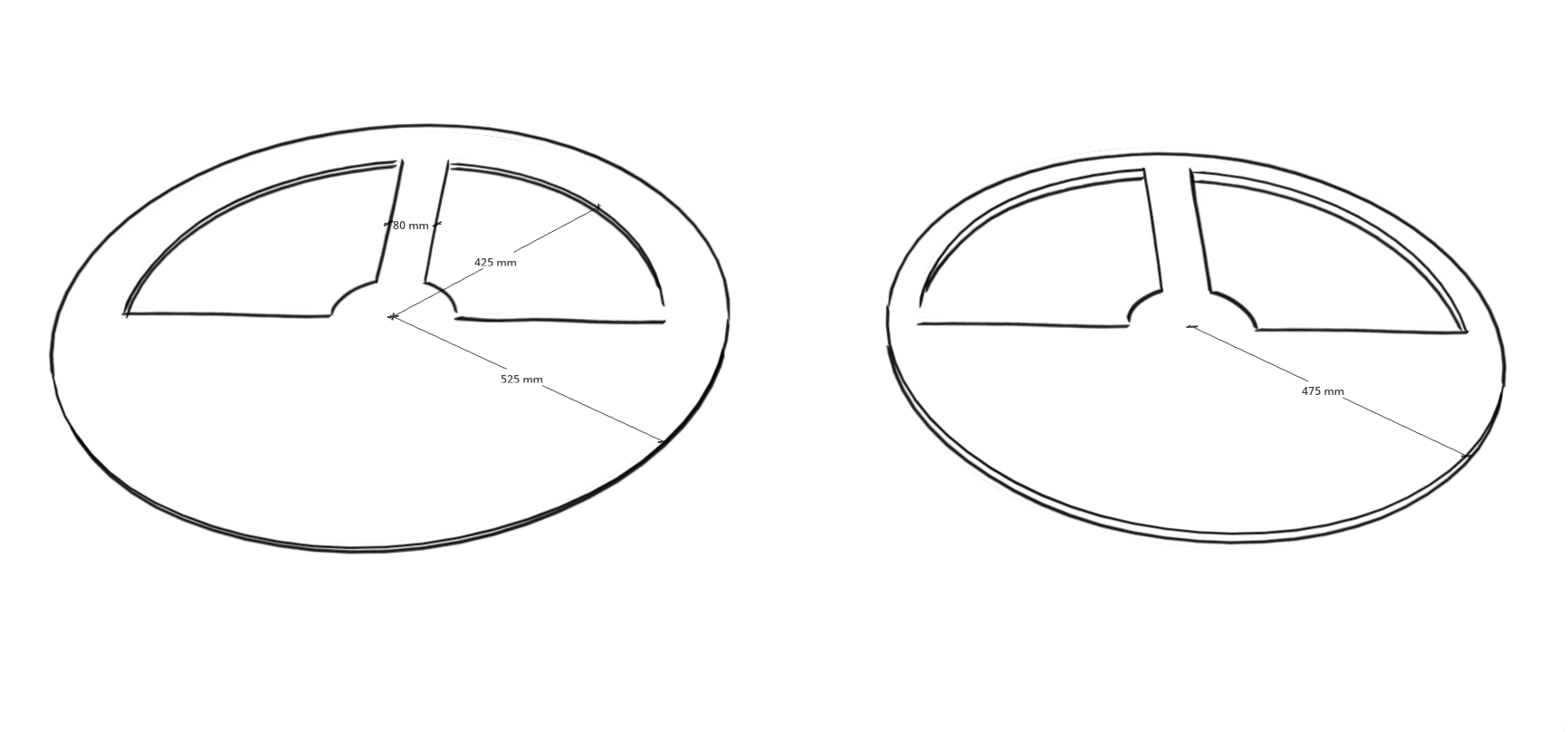
First, cut out two circles of 9mm MDF which will serve as the wheel rims. Then cut out three circles of 18mm OSB which will form the main body of the wheel. I used a length of wood as a compass. A screw at one end serves as the centre point and then drill three holes the diameter of a pencil to scribe the circles, one at 425mm for the cutout, one at 475mm for the inner layers and one at 525mm for the outer layers. It is important not to lose where the centre points are, which is easily done on the OSB, so press the compass point in firmly and mark with a small cross afterwards. Then using a fairly small drill bit(4mm) drill each centre as straight as possible. We will use this same drill bit to accurately key the pieces together when marking out the cutouts and doing the final assembly.
On one of the MDF sections(which will provide a crisper template) mark out the cutout sections as shown below and cut out using a jigsaw. Then using this as a master template, key this to each piece in turn and mark and cut all the remaining pieces.
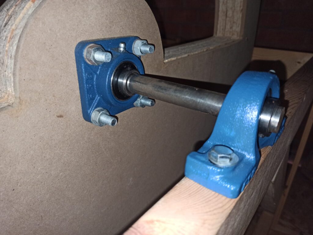
The wheel uses two 20mm flange bearings on the wheel and two 20mm pillow block bearings on the frame with a 20mm mild steel shaft. A larger hole needs to be drilled through the centre. This can be quite a bit bigger(24mm) as the flange block bearings will be holding the wheel. Holes also needs to be drilled for the flange bearings.
If you have the means to drill perfectly perpendicular holes then this can be done after the wheel has been complete but I chose instead to first drill the template and then use the template to drill each section in turn.
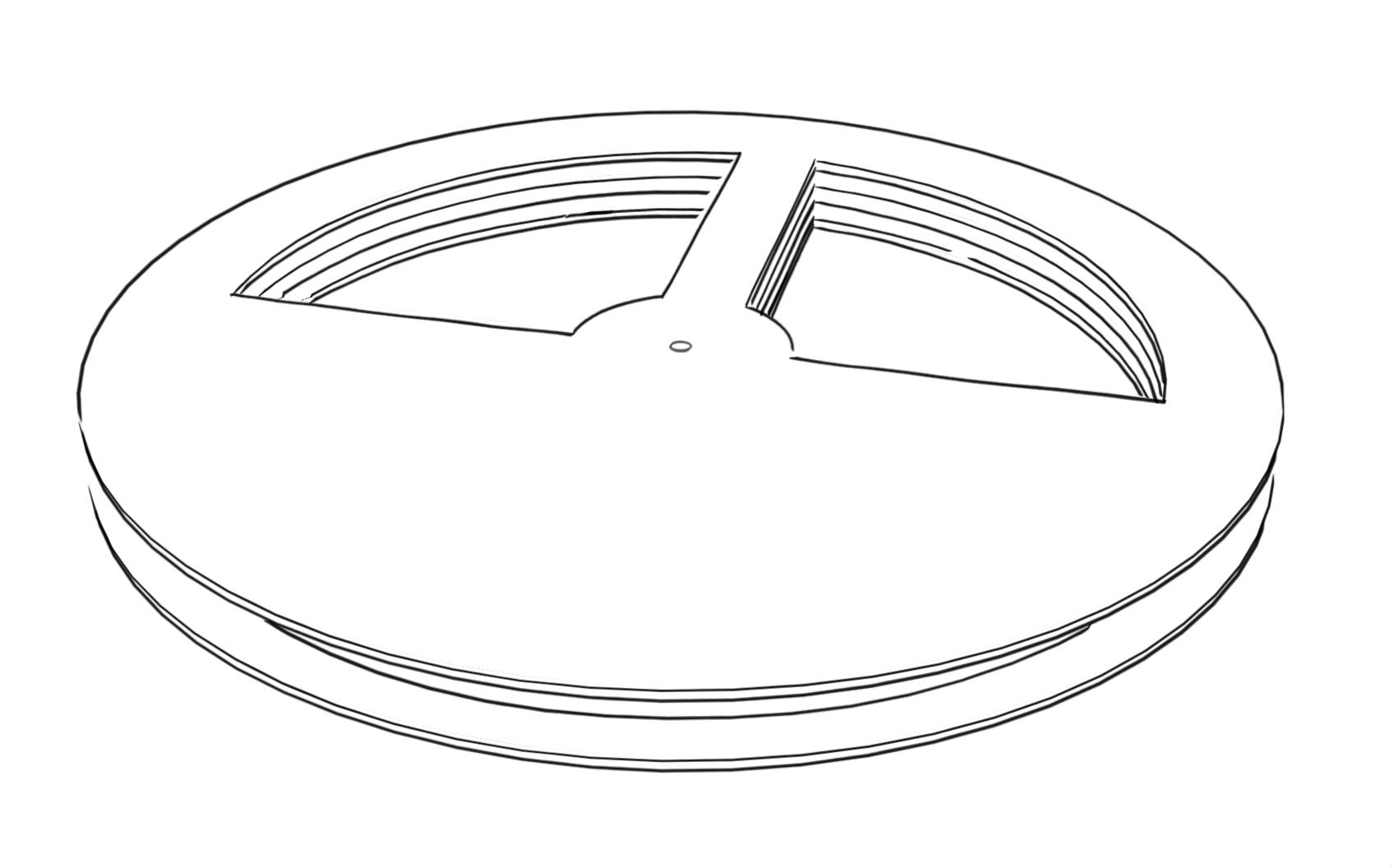
When all the pieces are prepared, stack together as above and rotate until all are aligned. You could choose to drill through at various location and bolt the layers together but I chose in the end to use screws from both sides.
Frame and putting it all together
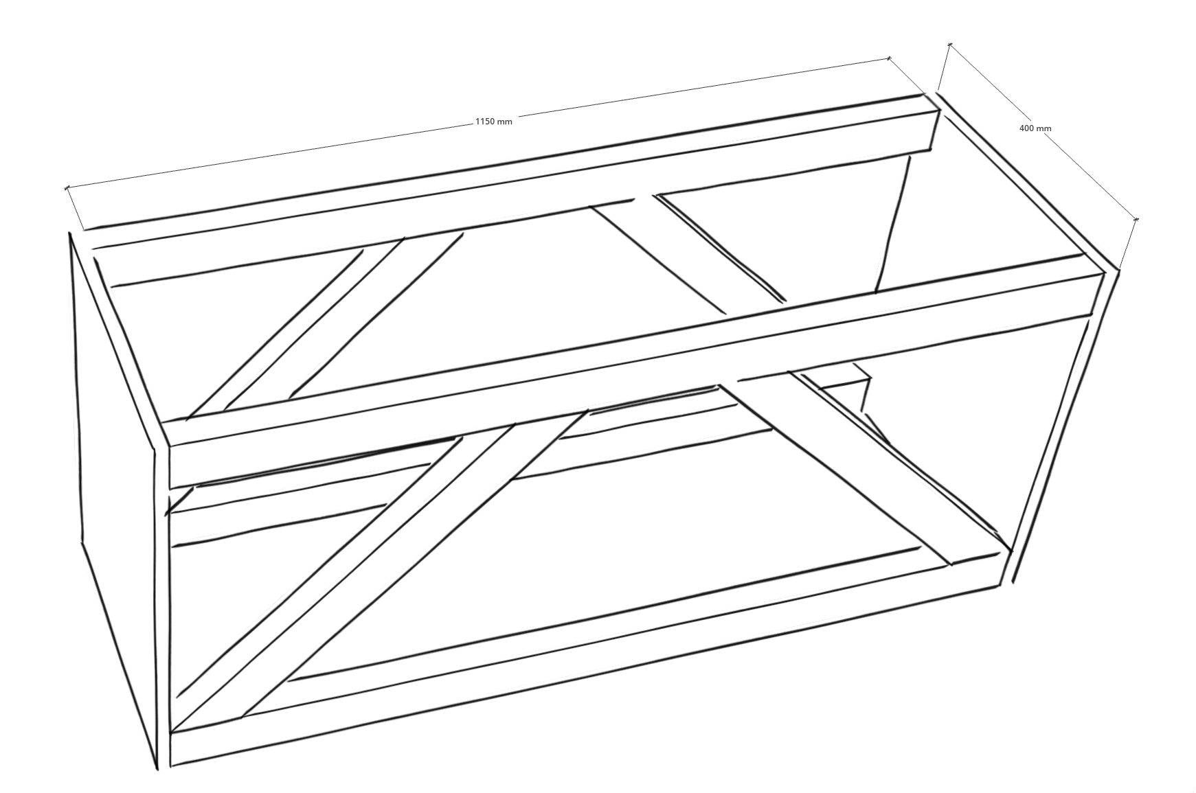
The next step is to create a frame and this could be done a number of ways but it needs to be sturdy. I would suggest 2 x 4s with two end plates made from the left over OSB. Test fit the wheel with axel and bearings and when you are happy you can screw in the bearings with some coach bolts and washers.
Ground Pulley
[UNDER CONSTRUCTION]
Materials:
Wheel:
2 sheets 18mm OBS (This will provide enough for the three inner sections of the wheel and the rest can be used for the end plates of the frame)
1 sheet 9 mm MDF
Frame:
2×3 x 4
Hardware:
40cm steel rod – 20mm dia
Pillow block bearings x 2
Flange bearings x 2
12 mm threaded rod
12mm Nyloc nuts x 8
Ground pulley
Misc:
Bell rope
Roof boss